473
views
0
recommends
+1 Recommend
1 collections
    0
    shares

      King Salman Center for Disability Research "KSCDR" is pleased to invite you to submit your scientific research to the "Journal of Disability Research - JDR", where the "JDR" comes within the Center's strategy aimed at maximizing the impact of research on the scientific field, by supporting and publishing scientific research on disability and its issues, which reflect positively on the level of services, rehabilitation, and care for individuals with disabilities.
      "JDR" is a scientific journal that has the lead in covering all areas of human, health and scientific disability at the regional and international levels.

      scite_
       
      • Record: found
      • Abstract: found
      • Article: found
      Is Open Access

      A Prospective Outlook on the Development of Exoskeletal Knee Joints for Prostheses via a Design Concept Evaluation Approach

      Published
      research-article
      Bookmark

            Abstract

            Disability is a complex multidimensional challenge and it can substantially limit the major life activities of a person. In the Kingdom of Saudi Arabia, it is estimated that 3.73% of the population have functional disabilities. People with disability always stay in the same posture which limits their social independence. A brief introduction and a literature review about exoskeletal prostheses and a preliminary analysis of the biomechanics of passive knees are presented in this paper. The proposed knee joint design has key features that are similar to other currently available knee joints for prosthetic legs. The main components of our design include single-axis knee joints, legs, and sockets. We limited our investigation to a handful of biomechanical variables that can be easily evaluated and generate some targets for long-term rehabilitation research. Thus, by following the cognitive principle of engineering design methodology, i.e. the “weight and rate criterion,” we provide a preliminary concept and theoretical calculations for the development of a cost-effective knee joint system. The Ansys engineering simulation and three-dimensional design software such as SOLIDWORKS simulation were utilized to provide an outlook of our initial prototype. In addition, by subjective and objective approaches, from our theoretical calculation for our designed product, the factor of safety was determined to be higher than 1.5.

            Main article text

            INTRODUCTION

            The loss of a body part has been witnessed from the beginning of the ages in humans, and this happens due to several reasons including diseases, accidents, and wars, and the cost of an artificial implant is very high at the moment for some members in the community. In injured patients, the lack of mobility for a long time can cause several medical and psychological issues. Patients around the world are now requiring implants that can last longer and provide less discomfort but at a reduced cost. The most comprehensive study found was the “Disability Survey 2017” report published by the General Authority for Statistics (GAStat) of Saudi Arabia in 2017. The GAStat surveyed a random sample of 33,575 households in a way that guarantees representation nationwide in 2017 to determine the demographics of people with physical and intellectual disability across Saudi Arabia [Putti, 1930; Miller, 1946; Engstrom and Van de Ven 1999; Ebnezar, 2000; Andrysek, 2010; May and Lockard 2011; Bindawas and Vennu, 2018]. According to the report, 1.6% of people in Saudi Arabia have extreme locomotor disability. Few studies have been published on the demographics of amputees in Saudi Arabia. Nowadays many artificial lower limbs are available on the market, and each one of them uses different mechanisms and materials, and the main factor between these artificial limbs is the mechanism of the knee joint, which are summarized in Table 1. Human movement is a biomechanically efficient process. A healthy person may travel vast distances while consuming little energy. Despite advancements in prosthetic design, replacing lower-limb segments with a prosthesis reduces mobility efficiency. The goal of a lower-limb prosthesis is to reduce the impact of the amputation and restore the patient’s independence. Hence, the prosthesis technology focuses on simulating the joint behavior of human lower limbs when walking. Therefore, understanding the gait cycle and the resulting mechanical forces that impact the whole cycle is crucial for designing exoskeletal devices. For people with transfemoral amputations, prosthetic knees are cutting-edge medical devices that use mechanical mechanisms and components to imitate the natural biological knee function [Preuss, 1911; American Academy of Orthopaedic Surgeons, 1960; Fliegel and Feuer, 1966; Padula and Friedmann, 1987; Hibbeler 1994; Shigley et al., 2004; Lambrecht 2008; Narang, 2013; Rodriguez-Merchan 2013; Bergmann et al., 2014; Kannenberg et al., 2014; Arelekatti, 2015; Pirker and Katzenschlager 2017]. By presenting a biomechanical overview of prosthetic knees, this article seeks to fill in this knowledge gap.

            Table 1:

            Summary of the different types of knee joints available on the market.

            NameSpecificationsTypeCost
            LIMBS Knee [Narang 2013]
            • Light weight

            • No advance technology

            • Short-life material

            • Low stability

            Four bar$20
            75 SR
            The 802 Nylon Knee [Arelekatti 2015]
            • Light weight

            • No advance technology

            • Handle weight up to 100 kg

            • Low maintenance and durability

            Single axis
            Hydraulic
            $2100
            7875 SR
            C-leg [Kannenberg 2014]
            • Highly stable

            • Advance technology

            • Handle weight up to 130 kg

            • Batteries live up 45 hours for one charge

            Single axis
            Microprocessor
            hydraulic
            $54,500
            204,375 SR
            Genium [Farina and Aszmann 2014]
            • Light weight

            • Advance technology

            • Handle weight up to 150 kg

            • Batteries live up 120 hours for one charge

            Single axis
            Microprocessor
            hydraulic
            $75,000
            281,250 SR

            METHODS

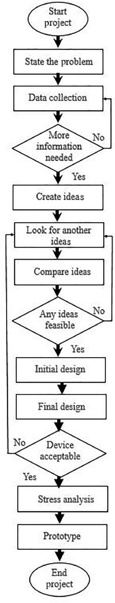
            This study presents an outlook on the designing of knee-related passive implants. The research methodology is subdivided into various categories. A schematic diagram explicitly indicating the outline of the sequence of steps that are followed for executing the present study is shown in Figure 1. In this paper, the salient results revealing the design of a knee implant according to durable biomechanical requirements are discussed. Furthermore, theoretical calculation encompassing the various structural components is also included. Also, we present ideas about three general trends in the current and future development of prosthetic knees in terms of the design project approach.

            The flowchart diagram of the participant activities by sequential step in the present project approach. Solid arrows represent the typical sequence of step utilized in the completion of the basic simulation and design process.
            Figure 1:

            Flow chart showing the sequence of steps involved in the present design project.

            RESULTS AND DISCUSSION

            Equilibrium analysis and theoretical design calculations

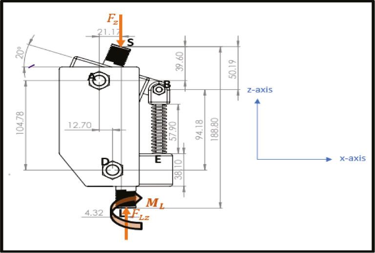
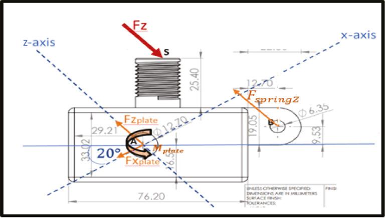
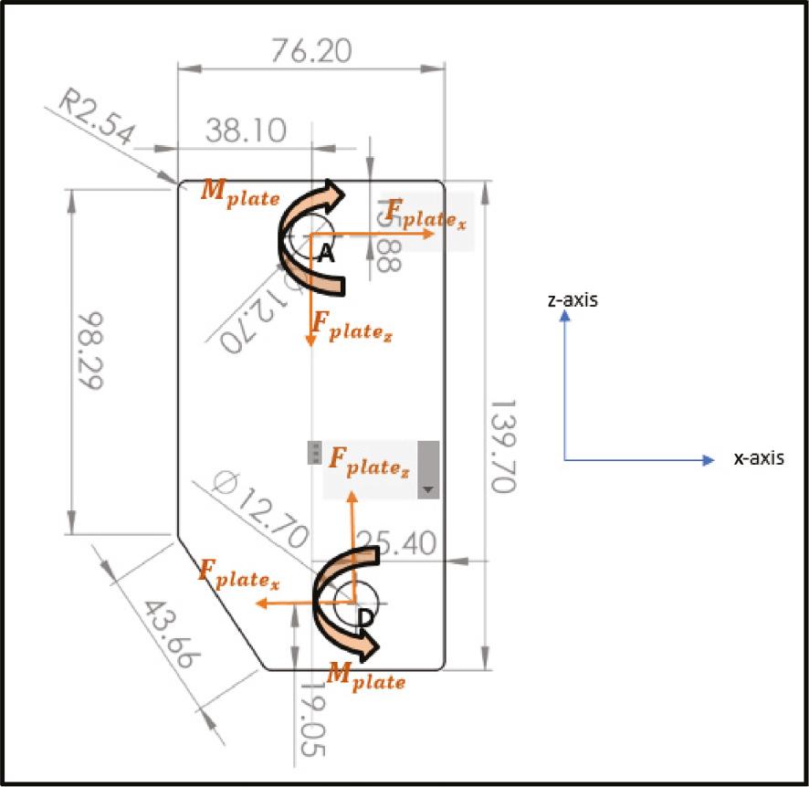
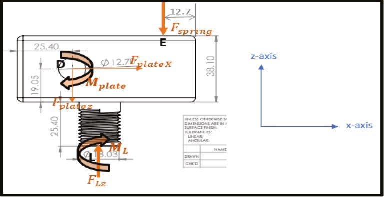
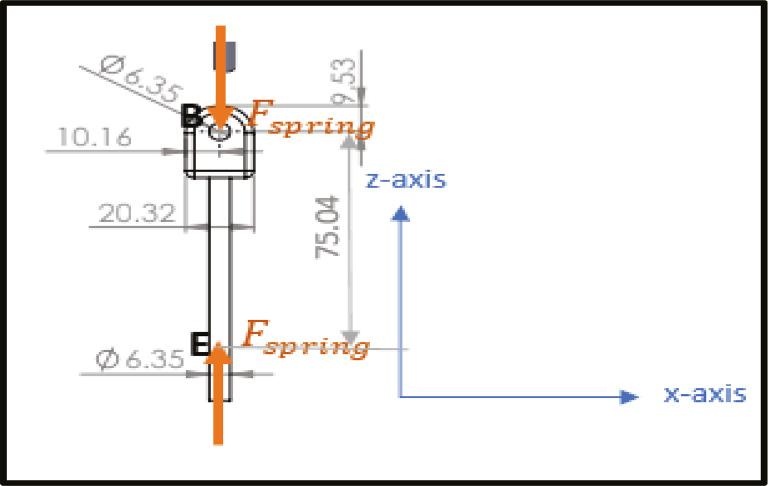
            For our study, we defined the maximum body weight as 100 kg. From the literature it is known that the maximum force acting on the knee during walking (gait cycle 55%, knee flexion angle 20°) is around Fz=3571 N . This shows that the forces on the other direction are very small compared to the force on the z direction as summarized in Table 2. In order to find out the amount of forces acting on the device, we divided the external load by 2, one for each side of the knee, and the free body diagram (FBD) of each section is presented in Figures 26, respectively.

            Fz=35712=1785.5 N

            From FBD-1:

            Fz=0

            FLZ=Fz=1785.5 N

            My at Point L=0

            ML=Fz×(4.321000)

            From FBD-2:

            My at Point A=0

            FSpringZ×571000+Mplate=Fz×21.171000

            Fz=0

            Fz=FSpringZ+Fplatez

            From FBD-3:

            My at Point A=0

            Mplate=Fplatez×12.71000

            From FBD-4:

            Fx=0

            FplateX=0

            Table 2:

            Summary of loads acting on knees and their equilibrium reactions.

            Type of loadForcesMoments
            UnitNewtonNewton-meter
            Name Fz FLZ FplateX Fplatez FSpringZ ML Mplate
            Value for one side1785.51785.501444341.47.71318.34
            Total value3571357101444682.815.42618.34
            Sketch of free body diagrams of the knee section showing the normal force acting on it.
            Figure 2:

            FBD-1 for the knee section. Abbreviation: FBD, free body diagram.

            Sketch of free body diagrams of the upper part of the connector section showing the force acting on it.
            Figure 3:

            FBD-2 for the upper connector section. Abbreviation: FBD, free body diagram.

            Sketch of free body diagrams of the plate section showing the force and moment acting on it.
            Figure 4:

            FBD-3 for the plate section. Abbreviation: FBD, free body diagram.

            Sketch of free body diagrams of the lower part of the connector section showing the force and moment acting on it.
            Figure 5:

            FBD-4 for the lower connector section. Abbreviation: FBD, free body diagram.

            Sketch of free body diagrams of the spring part of the device showing the force and moment acting on it.
            Figure 6:

            FBD-5 for the spring connector section. Abbreviation: FBD, free body diagram.

            Figures 7 and 8 summarize the force versus displacement and moment versus displacement charts, respectively.

            The figure shows the force vs. displacement graph, summarizing the amount of force applied to the designed device
            Figure 7:

            Force vs. displacement chart.

            The figure shows the Moment vs. displacement graph, summarizing the amount of moments applied to the designed device
            Figure 8:

            Moment vs. displacement chart.

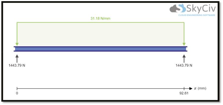
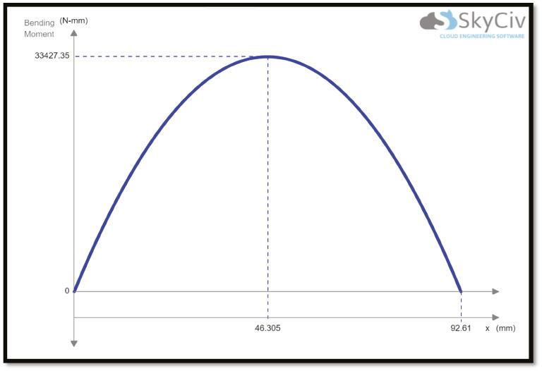
            Here, at the middle of the bar, we will have the critical point:

            Tmax=18.340 kNmm ,Mmax=33.42735 kNmm

            From the literature it is known that the load fluctuates from nearly 0 N to a maximum of 3571 N; so, we assumed that the force is between 0 load and 3571 N (repeated stress) to continue further analysis.

            For the bar material, we chose 1030 hot rolled steel, which has the following specifications [Ijaz et al., 2016]:

            Sut=470 MPa ,Sy=260 MPa

            We have no change in cross sections; therefore, we assume that any stress concentration factor = 0.

            Endurance limit Se calculations:

            d=12 mm

            I=π64×d4=π64×12410004=1.018×10⁹m4

            J=π2r4=2.035×10⁹m4

            Non-rotating:de=0.37d=0.37×12=4.44 mm

            Kb=1.24d0.107=1.24×120.107=1.057

            Ka=aSutb=4.51×2900.265=1.004

            Kc=Kd=Ke=kf=1

            Se=0.5Sut=0.5×470=235 MPa

            Se=SeKaKbKcKdKeKf=249.38 MPa

            Stress calculations:

            σmin=0

            σmax=MmaxcI=33.42735×610001.018×109=196.98 MPa

            τmax=TmaxcJ=18.34×610002.035×109=54.07 MPa

            σmax=(σmax)2+3(τmax)2=(218.1096) MPa

            σa=σmax2=109.05 MPa

            σm=σmax2=109.05MPa

            Fatigue factor of safety nf: 1nf=σaSe+σmSutnf=1.59>1

            Static factor of safety ny:ny=Syσa+σm=2.19>1  

            Endurance limit calculation for the rod used for constructing the leg

            For the leg rod material, we chose Al-6061 rolled, which has the following specifications [Ijaz et al., 2016]:

            Sut=290 MPa ,Sy=255 MPa

            We have no change in cross sections; therefore, we assume that any stress concentration factor = 0.

            Endurance limit Se calculations:

            For aluminum Al-T6061:

            σy=255 MPa ;  E=68.9 GPa

            For the rod:

            D=0.0281 m ;  L=0.4318 m ;K=1

            Effective length factor:

            Le=K×L=0.4318 m

            The moments of inertia for the leg:

            I=π64(0.028140.019054)=2.41×10⁸ m4

            The area of the cross section:

            A=π4(0.028120.019052)=3.35×10⁴m2

            Non-rotating:de=0.37d=0.37×0.0381=0.0141 m

            Kb=1.24d0.107=1.24×14.10.107=0.93

            Ka=aSutb=4.51×2900.265=1.004

            Kc=Kd=Ke=kf=1

            Se=0.5Sut=0.5×290=145 MPa

            Se=SeKaKbKcKdKeKf=136 MPa

            σmin=0

            ML=Mmax=15.426 MPa

            σmax=MmaxcI+FLzA=15.426×19.0510002.41×108+35713.35×104=19.65 MPa

            σmax=(σmax)2+3(τmax)2=19.65 MPa

            σa=σmax2=9.83 MPa

            σm=σmax2=9.83 MPa

            Fatigue factor of safety nf: 1nf=σaSe+σmSutnf=9.42>1

            Static factor of safety ny:ny=Syσa+σm=12.97>1  

            Buckling analysis of prosthetic pylon tubes

            Buckling is considered as the common mode of failure in the prosthetic pylon tube materials such as aluminum Al-T6061 [27].

            σy=255 MPa ;E=68.9 GPa

            For the rod:

            D=0.0281 m ;L=0.4318 m ;K=1

            Effective length factor:

            Le=K×L=0.4318 m

            The moments of inertia for the leg:

            I=π64(0.028140.019054)=2.41×10⁸ m4

            The area of the cross section:

            A=π4(0.028120.019052)=3.35×10⁴ m2

            Euler’s formula:

            Pcr=π2  E  ILe2=π2×68.9×109×2.41×1080.43182=87896.32 N

            σcr=PcrA=87896.323.35×104=262.38 Mpa 

            σallow=[2121.59(KLr)]=131.03 MPa

            σallowσcr     ;      n=2.21  

            Static analyses of helical spring design

            In this section, we will cover the design approach for the helical spring; there is a systematic method of designing starting with the number of constraints:

            The preferred range of the spring index is 4 ≤ C ≤ 12, with the lower indexes being more difficult to form (due to the risk of surface cracking) and springs with higher indexes tending to tangle often enough to require individual packing. This can be the first item for the design assessment. The recommended range of active turns is 3 ≤ N a ≤ 15. To maintain linearity, when a spring is about to close, it is necessary to avoid the gradual touching of coils (due to no perfect pitch). The rest of the constraints are stated below [Ijaz et al., 2016]:

            D=drod+d+allow

            4C12

            3Na15

            ξ0.15

            ns1.2

            Design assumptions

            After a number of iterations, the best design dimensions are stated below:

            d=2 mm

            D=8.55 mm

            Na=15 coils 

            Lo=58 mm

            After determining the primary dimensions, we performed the spring design calculations using the following equations:

            C=Dd=4.275

            KB=4C+24C3=1.354

            τs=8KB(1+ξ)Fmax.D(πd)3=293.17 MPa

            A helical compression spring is made of no. 30 music wire.

            Sut=Adm=221120.145=1999.58 Mpa

            Ssy=0.45Sut=0.45(1999.58)=899.81 Mpa

            Factor of safety ns=Ssyτs=3.069

            OD=D+d=10.55 mm

            ID=Dd=6.55 mm

            Na=15

            ymax.=Na.8D3Fmax.Gd4=39.51 mm

            Nt=10 total turns 

            Ls=d(Nt+1)=32

            (Locr)=Ls+(1+0.15)ymax.=77.43

            Using these equations, we determined the important factors such as spring rate k, the maximum applicable force on the spring Fmax , maximum spring displacement, maximum sheer stress, and the static factor of safety (FOS) against failure.

            Spring fatigue analysis

            Assumption unpeened spring (Ssa=241 MPa Ssm=379 MPa)

            Fa=Fm=Fmax.2=341.4 N

            τa=τm=8KBFa.D(πd)3=127.46 MPa 

            Sut=1999.58 Mpa 

            Ssu=0.67Sut=1339.71 MPa

            Sse=Ssa1(SsmSsu)2=261.96 MPa

            nf=Ssaτa=1.89

            Fatigue factor using Goodman: 1nf=τaSse+τmSsunf=1.719

            The results show that the spring can have infinite lives against fatigue.

            INTEGRATION OF SOLIDWORKS SIMULATION AND CALCULATIONS

            As we deduced from the calculation, the critical point will happen at gait cycle 55%, knee angle 20°, and Fz=3571 N . So, we studied this point in detail. The simulation results are summarized for each component and are shown in Figures 913, respectively.

            The figure shows the results of static simulation in solid works [3D solid modeling CAD software] for reaction forces and moments in the designed device.
            Figure 9:

            SW external load and reactions. Abbreviation: SW, SOLIDWORKS.

            The figure shows the results of finite element mesh [3D solid modeling CAD software] for the designed device.
            Figure 10:

            SW knee mesh. Abbreviation: SW, SOLIDWORKS.

            The figure shows the displacement result on the designed device analyzed by the use of finite element [3D solid modeling CAD software].
            Figure 11:

            SW knee displacement results. Abbreviation: SW, SOLIDWORKS.

            The figure shows the strain result on the designed device analyzed by the use of finite element [3D solid modeling CAD software].
            Figure 12:

            SW knee strain results. Abbreviation: SW, SOLIDWORKS.

            The figure shows the Von-Mises stresses result obtained on the designed device analyzed by the use of finite element [3D solid modeling CAD software].
            Figure 13:

            SW knee von Mises stress results. Abbreviation: SW, SOLIDWORKS.

            Knee

            So, the FOS of the spring [Shigley et al., 2004] is:

            ns=Syσspringmax=899 MPa197.8 MPa=4.55>1  

            So, the FOS of the knee is:

            ns=Syσkneemax=255 MPa140 MPa=1.82>1  

            The minimum FOS = 1.5 and it satisfies our specification.

            Ansys analysis
            Analysis for knee

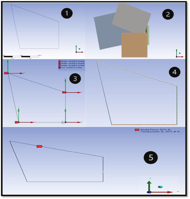
            To study the knee joint in Ansys, we created a simplified two-dimensional (2D) geometry that considers the links between the parts with the cross-section area of each component.

            Figure 14 presents the typical steps involved in Ansys simulations. Step (1) represents our geometry by simplifying the parts into 2D links. Step (2) represents the cross section of each part. Step (3) represents the connections between the links and which connection is fixed and which one is revolute. Step (4) represents the default mesh. Step (5) represents the external force acting on the upper connector of the knee.

            The figure shows the basic process of ANSYS Workbench simulation analysis result obtained on the designed device.
            Figure 14:

            Steps for Ansys simulation and analysis.

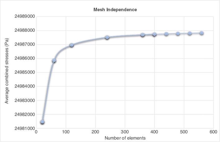
            To obtain a reasonable result, we need to perform a mesh independence study to check if the results are independent of the mesh or not; this is done by running multiple simulations with different meshes and checking if the results change.

            Figure 15 presents the average combined stress on the y-axis with increases in the number of elements on the x-axis. After 400 elements we can see that the line reaches an almost steady state, and changes in the output average combined stress become very small. Therefore, it is reasonable to take 480 elements.

            The figure shows an iterative method we increase number of elements along each side and stresses we develop a plot for stresses vs. the number of elements in the model utilized in the designed device.
            Figure 15:

            Knee mesh independence chart.

            So the FOS [Shigley et al., 2004] of the spring is:

            ns=Syσmax=899 MPa200 MPa=4.495>1   

            which is pretty similar to the spring ns of the SOLIDWORKS (SW) and the theoretical part. And due to the simplification of the body, there was no stress concentration for the thread. Therefore, we are taking into account only the FOS of the spring for this Ansys module.

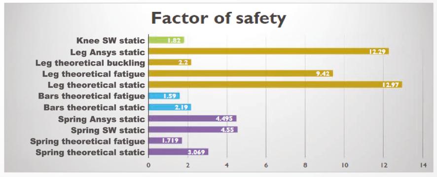
            Validation of the factor of safety

            These static FOSs are high and we can change the material for the static load. But, changing it to a cheaper material would affect the fatigue FOS, which barely met our specification. As our goal was to use a material with high strength and high stiffness, this material is sufficient for our application. As the two bars have the same boundary conditions, external forces, geometries, and material, calculating one of them is enough. Both the FOSs are acceptable according to our constraints. As the FOS is too high for the static and the fatigue, our material has a specification that exceeds the requirement. Therefore, we can adjust the area, but the height must be the same due to two reasons. One is that the buckling FOS is 2 and it depends on the height. Therefore, changing the height may result in an FOS less than 1.5. The other reason is that the height of the leg depends on the human body dimensions. So, if we change it, there will be no balance and the user will fall. The summary of the FOS for each component of the implant is presented in Figure 16. The complete customized initial design is shown in Figures 17 and 18, respectively.

            The figure shows the value of factor of safety for each component of the assembly derived after the calculation in the designed device.
            Figure 16:

            Summary of the factor of safety of each component. Abbreviation: SW, SOLIDWORKS.

            Customized design of the exoskeleton after manufacturing
            The figure shows the sometric illustration of the assembly showing all the part and manufactured knee joint
            Figure 17:

            Knee joint prototype.

            The figure shows the overview of front and side view of prototype design after manufacturing of the designed device.
            Figure 18:

            Initial design of the prototype.

            COST ANALYSIS

            Material cost

            The material cost of each part of the assembly as show in in figure as shown in Figures 17 and 18 respectively is estimated to be around 400 SR. The summary of the cost distribution for each component is presented in Table 3. The Al alloy or Ti-based alloys could be promising candidates for the manufacturing of these kind of devices [Ijaz et al., 2022, 2014, 2016, 2017; Ijaz and Hashmi 2022; Héraud et al., 2023].

            Table 3:

            Part unit cost vs. receipt cost.

            PartQuantityCost

            Plates
            218.79$
            70.50 SR

            Upper connector
            116.38$
            61.50 SR

            Lower connector
            117.45$
            65.50 SR

            Spring connector
            110.49
            $40 SR

            Spring
            13.21
            $12 SR

            Plates rod
            26.40
            $24 SR

            Spring connector rod
            12.84
            $11 SR

            Leg rod
            130.59
            $115 SR

            CONCLUSION

            In the present study, we concluded that our preliminary design could assist in solving problems that our community is facing in terms of the higher cost of artificial implants such as artificial limbs. We tried investigating the reason for the higher cost while looking at the existing products on the market, and we figured out that most of the products were designed using chips and microprocessors, which are good but they simultaneously increase the cost. To conclude, a summary of the present study is as follows:

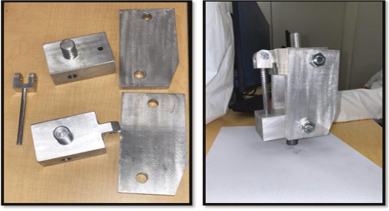
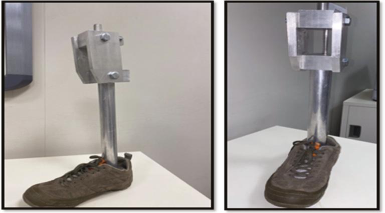
            1. We decided to design and fabricate an indigenous cost-effective artificial lower limb, following some constraints and criteria and the weight and rate methodology.

            2. We started our project by following the selection methodology until we came up with our final knee joint design which includes a single axis with a spring connecting to a leg rod.

            3. Using our knowledge from mechanical engineering, vital mathematical calculations were made to validate the FOS for our designed product.

            4. Ansys analysis and SW simulation were utilized to quantify the FOS and make sure it is higher than that we initially considered in the constraints. We proved that from all the methods our device is safe and the FOS is more than 1.5.

            5. After finalizing the design, we started choosing the material for the different parts of our product. As this designed knee implant will be in contact with the human body, we made sure that the material is biocompatible. Thus, we chose aluminum Al-6061 for the other parts of the knee joint and the leg rod.

            ACKNOWLEDGMENTS

            The authors extend their appreciation to the King Salman Center for Disability Research for providing funding for this work through Research Group number KSRG-2022-033.

            REFERENCES

            1. American Academy of Orthopaedic Surgeons. 1960. Orthopaedic Appliances Atlas. Volume 2: Artificial Limbs: A Consideration of Aids Employed in in the Practice of Orthopaedic Surgery. JW Edwards. Ann Arbor:

            2. Andrysek J. 2010. Lower-limb prosthetic technologies in the developing world: a review of literature from 1994–2010. Prosthet. Orthot. Int. Vol. 34(4):378–398

            3. Arelekatti VNM. 2015. Design of low-cost, fully passive prosthetic knee for persons with transfemoral amputation in India. Massachusetts Institute of Technology.

            4. Bergmann G, Bender A, Graichen F, Dymke J, Rohlmann A, Trepczynski A, et al.. 2014. Standardized loads acting in knee implants. PLoS One. Vol. 9(1):e86035

            5. Bindawas SM, Vennu V. 2018. The national and regional prevalence rates of disability, type, of disability and severity in Saudi Arabia—analysis of 2016 demographic survey data. Int. J. Environ. Res. Public Health. Vol. 15(3):419

            6. Ebnezar J. 2000. Textbook of Orthopaedics. Jaypee Brothers.

            7. Engstrom B, Van de Ven C. 1999. Therapy for Amputees. Elsevier Health Sciences.

            8. Farina D, Aszmann O. 2014. Bionic limbs: clinical reality and academic promises. Sci. Transl. Med. Vol. 6(257):257ps12

            9. Fliegel O, Feuer SG. 1966. Historical development of lower-extremity prostheses. Arch. Phys. Med. Rehabil. Vol. 47(5):275–285

            10. Héraud L, Castany P, Ijaz MF, Gordin DM, Gloriant T. 2023. Large-strain functional fatigue properties of superelastic metastable β titanium and NiTi alloys: a comparative study. J. Alloys Compd. Vol. 953:170170

            11. Hibbeler RC. 1994. Mechanics of Materials. MacMillan Publishing Company.

            12. Ijaz MF, Hashmi FH. 2022. Revisiting alloy design of Al-base alloys for potential orthotics and prosthetics applications. Crystals. Vol. 12(12):1699

            13. Ijaz MF, Kim HY, Hosoda H, Miyazaki S. 2014. Effect of Sn addition on stress hysteresis and superelastic properties of a Ti–15Nb–3Mo alloy. Scr. Mater. Vol. 72:29–32

            14. Ijaz MF, Laillé D, Héraud L, Gordin DM, Castany P, Gloriant T. 2016. Design of a novel superelastic Ti-23Hf-3Mo-4Sn biomedical alloy combining low modulus, high strength and large recovery strain. Mater. Lett. Vol. 177:39–41

            15. Ijaz MF, Dubinskiy S, Zhukova Y, Korobkova A, Pustov Y, Brailovski V, et al.. 2017. Novel electrochemical test bench for evaluating the functional fatigue life of biomedical alloys. JOM. Vol. 69:1334–1339

            16. Ijaz MF, Alharbi HF, Bahri YA, Sherif ESM. 2022. Alloy design and fabrication of duplex titanium-based alloys by spark plasma sintering for biomedical implant applications. Materials. Vol. 15(23):8562

            17. Kannenberg A, Zacharias B, Pröbsting E. 2014. Benefits of microprocessor-controlled prosthetic knees to limited community ambulators: systematic review. J Rehabil Res Dev. Vol. 51(10):1469

            18. Lambrecht BGA. 2008. Design of a Hybrid Passive-Active Prosthesis for Above-Knee Amputees. University of California. Berkeley:

            19. May BJ, Lockard MA. 2011. Prosthetics & Orthotics in Clinical Practice: A Case Study Approach. FA Davis. Philadelphia:

            20. Miller G. 1946. Bibliography of the history of medicine of the United States and Canada—1945. Bull. Hist. Med. Vol. 19(5):536–567

            21. Narang YS. 2013. Identification of design requirements for a high-performance, low-cost, passive prosthetic knee through user analysis and dynamic simulation. Massachusetts Institute of Technology.

            22. Padula PA, Friedmann LW. 1987. Acquired amputation and prostheses before the sixteenth century. Angiology. Vol. 38(2):133–141

            23. Pirker W, Katzenschlager R. 2017. Gait disorders in adults and the elderly: a clinical guide. Wien. Klin. Wochenschr. Vol. 129(3-4):81–95

            24. Preuss J. 1911. Biblisch-talmudische Medizin: Beiträge zur Geschichte der Heilkunde und der Kultur überhaupt. S. Karger. Basel:

            25. Putti V. 1930. Historic Artificial Limbs. Hoeber. New York:

            26. Rodriguez-Merchan EC. 2013. Special features of total knee replacement in hemophilia. Expert Rev. Hematol. Vol. 6(6):637–642

            27. Shigley JE, Mischke CR, Brown TH Jr. 2004. Standard Handbook of Machine Design. McGraw-Hill Education. New York:

            Author and article information

            Journal
            jdr
            Journal of Disability Research
            King Salman Centre for Disability Research (Riyadh, Saudi Arabia )
            30 May 2023
            : 2
            : 1
            : 47-62
            Affiliations
            [1 ]Mechanical Engineering Department, College of Engineering, King Saud University, Riyadh, Saudi Arabia
            [2 ]King Salman Center for Disability Research, Riyadh, Saudi Arabia
            Author notes
            Correspondence to: Muhammad Farzik Ijaz*, e-mail: mijaz@ 123456ksu.edu.sa ; farzik98@ 123456gmail.com
            Author information
            https://orcid.org/0000-0003-2338-023X
            Article
            10.57197/JDR-2023-0006
            3398950b-b9d3-42a8-8f5f-53d1a28bd4da
            Copyright © 2023 The Authors.

            This is an open access article distributed under the terms of the Creative Commons Attribution License (CC BY) 4.0, which permits unrestricted use, distribution and reproduction in any medium, provided the original author and source are credited.

            History
            : 29 January 2023
            : 01 May 2023
            : 09 May 2023
            Page count
            Figures: 18, Tables: 3, References: 27, Pages: 16
            Funding
            Funded by: King Salman Center for Disability Research for this work through Research Group
            Award ID: KSRG-2022-033
            The authors are grateful for the financial support provided by the King Salman Center for Disability Research for this work through Research Group number KSRG-2022-033.

            Social policy & Welfare,Political science,Education & Public policy,Special education,Civil law,Social & Behavioral Sciences
            theoretical calculations,preliminary study,exoskeletal implant,factor of safety

            Comments

            Comment on this article