- Record: found
- Abstract: found
- Article: found
Chemical Bonding and Atomic Structure in Y 2O 3:ZrO 2-SrTiO 3 Layered Heterostructures**
research-article
Read this article at
There is no author summary for this article yet. Authors can add summaries to their articles on ScienceOpen to make them more accessible to a non-specialist audience.
Abstract
Deposition of nanosized layers of two different metal oxides upon one another produces
layered heterostructures with a wide range of new physical properties.1 For example,
a conducting two-dimensional electron gas was discovered at the interface between
the two insulators LaAlO3 and SrTiO3.2 The atomic arrangements within heterostructures
of complex functional oxides determine the resulting properties and are not necessarily
straightforward to construct based on the bulk crystal structures of the independent
components.
García-Barriocanal et al. reported that an epitaxial heterostructure of nanometer-sized
layers of Y2O3-stabilized ZrO2 (YSZ) and [001]-oriented SrTiO3 (STO) has an up to
eight orders of magnitude higher conductivity than bulk YSZ at room temperature.3
YSZ is a commonly used electrolyte in solid oxide fuel cells (SOFCs) run at high temperatures
(>800 °C), and such an increase in ionic conductivity at lower temperatures would
be expected to have a substantial impact on the performance of SOFCs.4 However, considerable
discussion has followed the original publication, with the suggestion that the increased
conductivity may be partly electronic in origin.5 The possibility remains that the
conductivity is entirely ionic6 with indications that the increased conductivity arises
from disorder in the oxygen lattice induced in the YSZ layers.7, 8 Similar, though
smaller, increases in conductivity have been found for other layered oxide heterostructures.9
The exact atomic structure of the YSZ-STO heterostructures remains undetermined. Knowledge
of the structure at the boundary between the two component oxide units is crucial
for understanding the increase in conductivity, which has been assigned to reconstruction
at this interface within the structure.3 It is difficult to probe the structure of
interfaces within thin films experimentally, and previous attempts for YSZ-STO films
seem inconsistent. The relative orientation of the YSZ and STO regions has been determined
by X-ray diffraction10 and scanning transmission electron microscopy,3, 8 with YSZ
rotated by 45° about the [001] axis relative to STO. However, electron energy loss
spectroscopy suggests that the STO is terminated with a TiO2 layer3 in layered YSZ-STO,
whereas experimental attempts to grow YSZ on STO substrates with different terminations
show that [001]-oriented YSZ can only be reliably grown epitaxially on SrO-terminated
STO,10 leaving the preferred termination of the STO in question. Previous calculations,
carried out using only TiO2-terminated STO,7 determined that oxide ions in the first
YSZ layer adopted positions completing the TiO6 octahedra. We assess the stability
and electronic structure of different possible atomic arrangements in the YSZ/STO
heterostructure using density functional theory (DFT) calculations, focussing on reconstruction
at the repeating boundaries between the component YSZ and STO units. We find that
the most stable structures, and those which correspond to known oxide crystal chemistry,
are not obtained by taking bulk terminations of the YSZ and STO crystals. Instead
taking a rock-salt ordered ZrO termination of YSZ gives stable structures with coordination
environments which are consistent with known crystal structures, while maintaining
insulating electronic behavior and correct YSZ stoichiometry. We have chosen to use
DFT calculations, unlike recent classical force field calculations of heterostructures
containing YSZ.11 Although DFT calculations are limited to smaller cells than those
used in classical simulations, and are therefore not able to investigate the micrometer
scale, they are more transferable than force fields. This is desirable for our structural
investigation, since atoms in heterostructures are likely to be in coordination environments
different from the constituent bulk phases. Additionally, DFT calculations allow for
flexibility in the oxidation state of atoms, and for the calculation of the electronic
properties of heterostructures.
The simplest model for the buried interfaces within layered heterostructures of two
materials is to use terminations of their bulk crystal structures at the interfaces.
The two possible terminations in the [001] direction for each of the STO (perovskite)
and YSZ (fluorite) crystal structures are shown in Figure 1: STO terminates with either
SrO layers or TiO2 layers (both neutral), and YSZ with either Zr or O2 layers (both
charged: neglecting Y atoms and O vacancies). This yields four possible interfaces
(Figure 2): A) Zr-terminated YSZ and TiO2-terminated STO, B) Zr-terminated YSZ and
SrO-terminated STO, C) O2-terminated YSZ and TiO2-terminated STO, and D) O2-terminated
YSZ and SrO-terminated STO.
Figure 1
a) The perovskite crystal structure and b) the SrO- and c) TiO2-terminations of SrTiO3
in the [001] plane. d) The fluorite crystal structure and e) the Zr- and f) O-terminations
of cubic ZrO2 in the [001] plane. The fluorite unit cell has been rotated by 45° in
(e) and (f) to aid comparison with the perovskite terminations in (b) and (c) and
consists of sequential charged Zr4+ and O2
4− layers. The ZrO termination of ZrO2 used to construct models E and F has the same
structure as (b), where Sr is replaced with Zr. Ti atoms are at the center of the
gray polyhedra, other atoms are colored as follows: Sr mid-gray, Zr light gray, and
O dark gray.
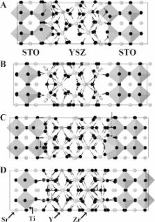
Figure 2
Structural diagrams of the heterostructures formed using A) Zr-terminated YSZ and
TiO2-terminated SrTiO3, B) Zr-terminated YSZ and SrO-terminated SrTiO3, C) O2-terminated
YSZ and TiO2-terminated SrTiO3, and D) O2-terminated YSZ and SrO-terminated SrTiO3.
Each structure is viewed along one of the short lattice vectors. Ti atoms are at the
center of the gray polyhedra, other atoms are colored as follows: Sr mid-gray, Zr
light gray, Y dark gray, and O black. Open arrows indicate five-fold coordinated Zr
atoms at the interfaces between the STO and YSZ components. Down arrows indicate O–O
bonds. A and C with TiO2-terminated SrTiO3 have non-octahedrally coordinated TiO.
The construction of heterostructures containing each of these four interfaces is described
in detail in the Supporting Information. We used symmetric blocks of STO and YSZ,
with the same termination at each end, giving heterostructures with two equivalent
interfaces. This is in agreement with experiments, which show no difference between
interfaces on either side of YSZ/STO layers.3, 8 The correct choice of symmetric block
is essential to obtain chemically reasonable models. The YSZ block was constructed
according to the results of previous calculations.12 Both STO and YSZ blocks do not
have the overall composition of their bulk phases, since the terminating layer is
inevitably present in excess. The STO and YSZ blocks are 1–2 nm thick. Experimentally
layered heterostructures have been grown with 1 nm thick YSZ layers and 10 nm thick
STO.3 As 10 nm thick STO blocks are computationally infeasible at the level of theory
used here, and the centers of the computational STO blocks already resemble bulk STO
(see Table S1 in the Supporting Information), we consider our structures to be good
approximations of the structures of experimental materials.
Geometry optimization of each heterostructure was performed using periodic DFT,13
and as an indication of the relative stability of each heterostructure, a heat of
formation was calculated with respect to the binary oxides, as described in the Supporting
Information. The lowest energy structure for each of the four heterostructures, A–D,
is shown in Figure 2. The calculated energies were 26.3, 27.1, −0.5, and −5.1 eV for
A–D, respectively, with lower values representing more stable structures.
Structures A and B, with Zr-terminated YSZ blocks, are clearly unstable. The Zr(Y)
and O2 layers of YSZ are formally charged, whereas the SrO and TiO2 layers of STO
are charge neutral. As a result, the symmetric blocks of YSZ built with bulk terminations
are formally charged. With Zr-terminated blocks, the additional layer of Zr atoms
gives a composition of [Y2O3][ZrO2]14Zr4 for the YSZ block, with four excess Zr4+
ions. The calculations impose charge neutrality within the super-cells, which therefore
have more electrons than expected for the ions Sr2+, Ti4+, Y3+, Zr4+, and O2−. Plots
of the partial density of states (PDOS) of A and B (Figure S2 in the Supporting Information)
show that the excess electrons populate Zr states within the band gap, and begin to
fill the Ti-dominated conduction band. This reduction of Zr4+ and Ti4+ to Zr3+ and
Ti3+ is clearly energetically expensive, leading to the instability of these models.
The interfaces within A and B also suggest energetically unstable structures. The
Ti octahedra terminating the STO block in A (Figure 2 A) are clearly distorted, in
some the Ti atom is only five-fold coordinated, in a square-pyramidal geometry. The
Zr atoms at the interface in B are similarly under-coordinated with most only bonded
to five O atoms (Figure 2 B). To our knowledge five-coordinate Zr is unknown in oxide
crystal structures.
In contrast, structures C and D, are constructed using O2-terminated YSZ blocks. These
structures represent most closely those proposed in earlier experimental studies.
García-Barriocanal et al.3 proposed TiO2-terminated STO and O2-terminated YSZ, similar
to structure C. Structure D, with SrO-terminated STO and O2-terminated YSZ, is effectively
that proposed by Cavallaro et al.10 with an interface region resembling SrZrO3. Both
models have YSZ blocks with composition [Y2O3][ZrO2]18O8. Considering the expected
oxidation states of all the ions, the eight excess O atoms result in electron deficient
charge-neutral super-cells. However the plots of the partial density of states (PDOS,
Figure S2 in the Supporting Information) do not show unoccupied states at the top
of the valence band as might be expected. Instead O–O bonding is present in the relaxed
structures of C and D. Structure C contains eight O–O bonds of lengths 1.4–1.5 Å in
the interface region, causing over coordination of Ti atoms, evident in Figure 2.
This O–O bonding completely accounts for the electron deficiency in the super-cell.
Similarly, structure D contains six O–O bonds of 1.5 Å length, with an extra O in
the Zr layers closest to the interface. Again, this largely accounts for the electron
deficiency in the super-cell, however with only six and not eight O–O bonds, the valence
band is now partially occupied (Figure S2 in the Supporting Information). No other
structure presented herein contained O–O distances shorter than 2 Å.
Using symmetrical unreconstructed Zr- and O2-terminated YSZ blocks clearly leads to
heterostructures which do not follow conventional solid-state chemistry. They are
either reduced in the case of Zr excess, or contain O–O bonds in the case of O excess.
It is, however, possible to construct symmetric YSZ blocks which are formally charge
neutral. Adding O to each end of Zr-terminated YSZ blocks (Figure 1 e), gives rock-salt
ordered ZrO terminating layers, similar to the SrO layers in STO (Figure 1 b, and
Figure S3 in the Supporting Information) and as observed experimentally for the surface
of YSZ.14 The resulting symmetric ZrO-terminated YSZ blocks have the composition [Y2O3][ZrO2]18,
and thus have neither excess Zr nor excess O. The ZrO-terminated YSZ blocks were combined
with TiO2- and SrO-terminated STO blocks giving structures E and F, respectively.
The final structures, optimized as for A–D, are shown in Figure 3.
Figure 3
Structural diagrams of the interfaces formed within an STO-YSZ heterostructure using
a ZrO-terminated YSZ block (depicted in Figure S3 in the Supporting Information) and
E: TiO2-terminated and F: SrO-terminated SrTiO3. To best display these two important
structures, each structure is viewed along both of the two short lattice vectors,
rather than just one. Ti atoms are at the center of the gray polyhedra, other atoms
are colored as follows: Sr mid-gray, Zr light gray, Y dark gray, and O black.
The calculated heats of formation for E and F were −2.5 and −6.7 eV, respectively.
Structure E is more stable than the other two heterostructures with TiO2-terminated
STO (A: 26.3 eV and C: −0.5 eV), and structure F is more stable than those with SrO-terminated
STO (B: 27.1 eV and D: −5.1 eV). The heterostructure with SrO-terminated STO, F, is
more stable than E, in good agreement with experimental observations that epitaxial
growth of [001] oriented YSZ was only seen with SrO-terminated STO substrates.10
Models E and F show none of the structural problems found in A–D. The PDOS plots in
Figure 4 show that both are undoped semiconductors, and no O–O bonds are present in
their structures. The calculated gaps (E: 1.78 eV, F: 1.37 eV) are similar to the
calculated gap of STO (1.79 eV) which is smaller than that of YSZ. We therefore consider
E and F to be the best representative models of YSZ-STO heterostructures proposed
to date. We emphasise that they require reconstruction of the terminal layer of the
YSZ block away from the bulk termination.
Figure 4
Partial density of states of structures formed with ZrO-terminated YSZ and E) TiO2-terminated
and F) SrO-terminated SrTiO3. Both materials have significant band gaps (DOS=density
of states).
A closer look at the structures of E and F in Figure 3 shows a surprising level of
order at the interfaces between YSZ and STO, particularly the left-hand interface
of E, and the right-hand interface of F. The first layers of YSZ at these two interfaces
appear well ordered, although the other interfaces are less so. Furthermore, all of
the Zr atoms in the YSZ layers directly neighboring the interfaces are seven-fold
coordinate. This is the preferred coordination number of Zr in baddeleyite (monoclinic
ZrO2),15 and an entirely reasonable coordination environment for the Zr atoms. In
agreement with earlier work,7 we find that the Ti atoms in E are octahedrally coordinated.
The YSZ terminating ZrO layer effectively caps the TiO2-terminating layer of STO continuing
the perovskite structure with Zr in the A-site. In F, the terminating ZrO layer lies
above the SrO-terminating layer of STO in a rock-salt like geometry resembling the
layers of neighboring perovskite blocks in Ruddlesden–Popper structures.16 Thus, in
both E and F, the ordered interfaces can be described in terms of simple, well-known
structural motifs for metal oxides.
The central region of YSZ in both E and F appears considerably less ordered than at
the interfaces. This disorder is largely due to the strain imposed on the YSZ by the
STO substrate, consistent with previous work.7, 8 Comparison of bulk YSZ structures
calculated with and without strain in Figure S1 in the Supporting Information, clearly
shows the deviation from the fluorite structure upon the application of strain. One
indication of this structural change is the alteration in the number of Zr and Y atoms
bonded to each O. In unstrained YSZ this is four for each O atom, as expected in the
fluorite structure. With the application of strain this drops to an average of 3.7
for bulk YSZ, similar to the values of 3.6 and 3.9 for the YSZ regions of E and F
(neglecting O atoms at the interface). Similarly the average number of O atoms bonded
to Zr and Y atoms drops from 7.8 in unstrained YSZ to 7.2 in strained YSZ and 7.1
and 7.3 in E and F. Although it is tempting to relate this change away from the fluorite
structure to the increased ionic conductivity seen experimentally, we note that the
O and Zr environments are in fact becoming close to those found in the most stable
ZrO2 polymorph, baddeleyite. Baddeleyite has a distorted fluorite structure with an
average of 3.5 Zr atoms bonded to each O atom, and each Zr atom coordinated to 7 O
atoms,15 and YSZ in this structure does not have a greater ionic conductivity than
cubic YSZ.17 Previous calculations on strained YSZ do suggest enhanced O diffusion,
however not sufficient to fully account for the increased ionic conductivity observed
in YSZ-STO heterostructures.18 In contrast to the YSZ region, the central STO region
in all models remains largely unchanged (Table S1 in the Supporting Information),
retaining the perovskite structure.
The results of this study suggest that the buried YSZ-STO [001] interfaces within
the heterostructure require reconstruction during the growth process of the component
structures to permit energetically stable and crystal-chemically acceptable structures
to form. We also confirm that the most stable heterostructure is formed with YSZ and
SrO-terminated STO, in agreement with experiment.10 The structures proposed here can
be used in calculating properties relevant to ionic transport, such as the influence
of oxygen defects, or the concentration and site preference of Y atoms (in particular
their proximity to the YSZ-STO interface), or molecular dynamics simulations. The
prediction of possible structures could also be an aid to further experimental characterization
of YSZ-STO heterostructures. It is interesting to note the relative stability of structures
containing excess oxygen at the interface (models C and D), compared to those with
oxygen deficiency (models A and B). This suggests further research into the possible
contribution of excess oxygen at YSZ-STO interfaces to increased ionic conductivity.
This study shows the benefit of choosing alternative terminations to the simple bulk
terminations of materials when constructing repeating buried interfaces in artificial
heterostructures. This is consistent with the known reconstruction of oxide surfaces,
including YSZ[001]14, 19 and STO[001]20 but distinct as in a heterostructure the interfaces
are buried. Our findings are relevant for such buried interfaces in many heterostructures,
particularly those with layers which are not charge neutral such as A(III)B(III)O3
perovskites and materials with the fluorite structure.
Related collections
Most cited references44
- Record: found
- Abstract: found
- Article: found
Rapid planetesimal formation in turbulent circumstellar discs
- Record: found
- Abstract: not found
- Article: not found
Generalized Gradient Approximation Made Simple.
Gary H. Perdew, Ernzerhof, M Perdew … (1997)
- Record: found
- Abstract: found
- Article: not found
Materials for fuel-cell technologies.
B. Steele, A. Heinzel (2001)